In This Topic
Shapes dropped to the drawing view from the library browser by default contain one or more ports, so you can easily attach connectors to them. If you create a shape using MyDraw's drawing tools or want to add more ports to your shape, you should right-click the shape and select Shape Properties. The following dialog will open:
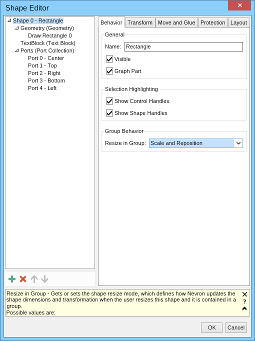
The tree view at the left side of the dialog shows the shape children, and the controls at the right side let you edit the properties of the item currently selected in the tree view.
Info panel
The info panel at the bottom of the dialog shows information about the currently edited (focused) property. For example, the screenshot above it shows information about the Resize in Group property of the shape. When the property info panel is not large enough to show the property description, it displays an arrowhead pointing upwards, as shown on the screenshot. Click it to expand the info panel and see the full description for the currently edited property.
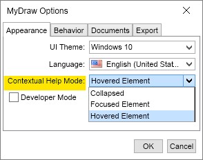
To switch the contextual help mode of the application and show information not for the currently edited property but for the property the mouse cursor is over, click the question mark button of the info panel. Click it again to switch back to focused element contextual help mode.
If you don't need contextual help in property editors, click the Close (the 'X') of the info panel to close it. You can later enable the info panel again from the General tab of the program options (File -> Options).
Add and remove ports
If the shape does not have any ports, the ports collection may not be present, too, and you will have to create it. To do so, select the shape in the tree view and click the Add button ( ) in the toolbar placed below the tree view. In the dialog that opens, select Ports (Port Collection) for the child type, and a port collection will be added for the shape. Then select the ports collection in the tree view and use the Add button to add one or more ports.
When you add a port, the easiest way to configure its location is to select the Relative check box to make its position relative to the shape bounds and then set the X and Y fields in the Location group box to values from 0 to 1, where (0, 0) denotes the top left corner of the shape's bounding box and (1, 1) denotes its bottom right corner. For example, to create a port at the center of the right side of the shape's bounding box, you should set X to 1 and Y to 0.5.
To remove a port, select it in the tree view, click the Delete button ( )from the toolbar, or press the Delete key from the keyboard.